Porisma

Vectors: magnitude, direction and products

← Back to learning units · Complete chapter reading and print view · Open reference notes separately

By the end, you can

  • Use displacement, magnitude and unit vectors
  • Interpret dot and cross products geometrically
  • Apply vectors to collinearity and projection

an hour and a half for the lesson · practise at your own pace.

The central idea

A vector combines magnitude and direction. The displacement from A to B is b−a\mathbf b-\mathbf a. The dot product a⋅b=∣a∣∣b∣cos⁡θ\mathbf a\cdot\mathbf b=|\mathbf a||\mathbf b|\cos\theta measures alignment; a zero dot product means perpendicular nonzero vectors. The cross product is perpendicular to both vectors and its magnitude gives parallelogram area.

Vector vocabulary and normalisation

A directed segment represents a vector: its length is the modulus ∣a∣|\mathbf a| and its arrow gives direction. The zero vector has zero magnitude. Two nonzero vectors are parallel precisely when a=kb\mathbf a=k\mathbf b for a nonzero real k. The vector −a-\mathbf a has the same magnitude and opposite direction.

For a≠0\mathbf a\ne\mathbf0, a^=a/∣a∣\widehat{\mathbf a}=\mathbf a/|\mathbf a| has unit magnitude and a=∣a∣a^\mathbf a=|\mathbf a|\widehat{\mathbf a}. A vector of magnitude 6 in that same direction is 6a^6\widehat{\mathbf a}. The zero vector cannot be normalised. These definitions extend the magnitude/direction view to points, lines and planes.

Vector notation, opposites and unit directions

Expand diagram

Use the scrollbars or arrow keys to inspect details.
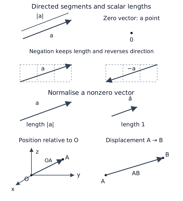
Source roles from pages 2–3: directed a and its scalar length; a and −a on equal grids; a nonzero a and its unit direction; position OA relative to origin and displacement AB between two points. Illustrations are schematic, with no added numerical conditions.
Open original diagram (new tab)

Equal free vectors at different locations

Expand diagram

Use the scrollbars or arrow keys to inspect details.
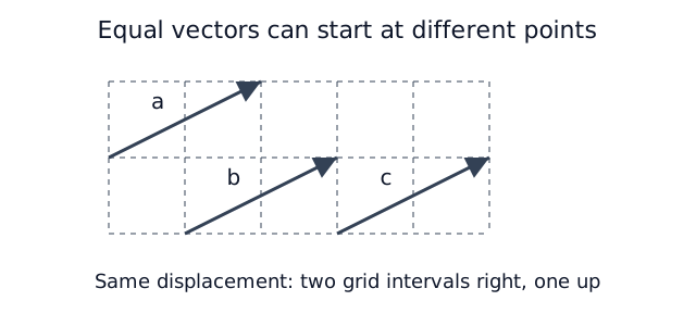
Three arrows a,b,c have identical displacement of two grid intervals right and one up, at different initial points. Their equal lengths and directions make them equal free vectors.
Open original diagram (new tab)

Triangle law of addition

Expand diagram

Use the scrollbars or arrow keys to inspect details.
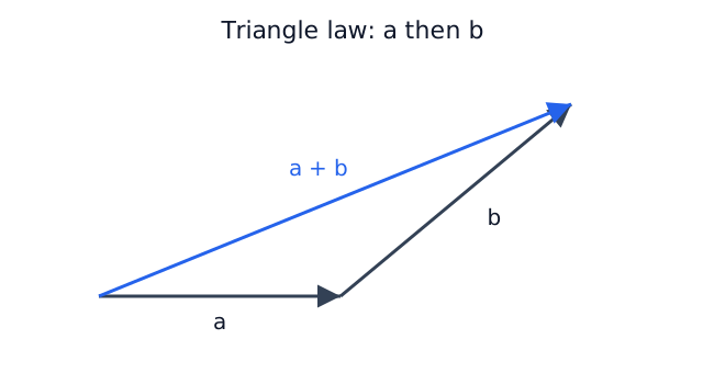
Place b’s tail at a’s head. The directed diagonal a+b joins the initial tail to the final head, matching the page 3 source triangle.
Open original diagram (new tab)

Commutative and associative addition paths

Expand diagram

Use the scrollbars or arrow keys to inspect details.
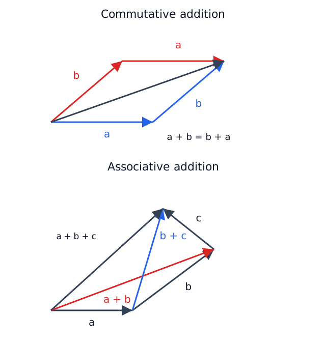
Top: routes a then b and b then a around a parallelogram have the same resultant. Bottom: a then b then c has intermediate diagonals a+b and b+c; both groupings give the same final displacement.
Open original diagram (new tab)

Subtraction and signed scalar multiplication

Expand diagram

Use the scrollbars or arrow keys to inspect details.
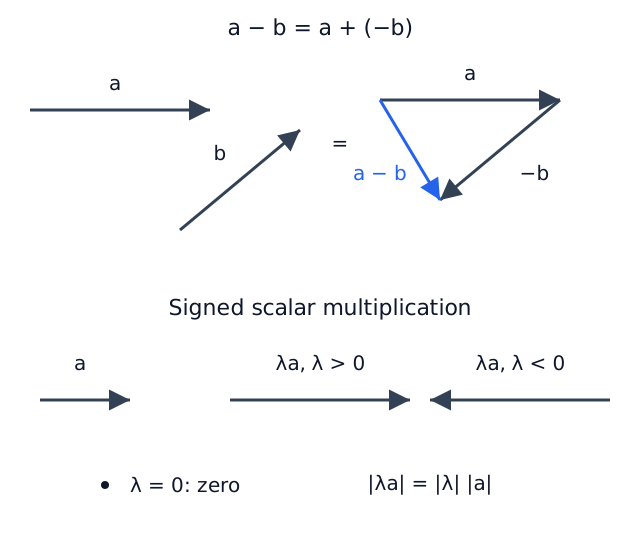
The source subtraction reverses b and adds −b to a, giving a−b. Positive scalar multiplication keeps direction, negative scaling reverses it; zero scaling gives zero. Length illustrations are schematic.
Open original diagram (new tab)

Position, displacement and translation in two dimensions

Expand diagram

Use the scrollbars or arrow keys to inspect details.
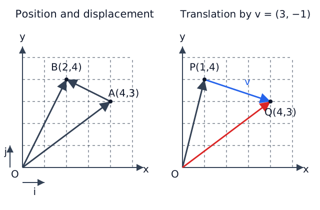
Equal-scale xy grids. Left: A(4,3),B(2,4), position arrows OA, OB and displacement A→B, with unit i,j. Right: P(1,4) maps to Q(4,3) by v=(3,−1); OP+v=OQ.
Open original diagram (new tab)

Three-dimensional coordinate decomposition

Expand diagram

Use the scrollbars or arrow keys to inspect details.
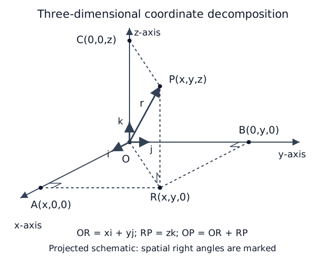
Schematic source projection: A(x,0,0),B(0,y,0),C(0,0,z),R(x,y,0),P(x,y,z), mutually perpendicular coordinate axes and basis i,j,k. Dashed projections and right-angle markers show OR in the xy-plane and RP parallel to z; OP is the resultant.
Open original diagram (new tab)

Right-handed coordinate directions

Expand diagram

Use the scrollbars or arrow keys to inspect details.
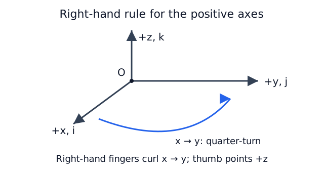
Curl the right-hand fingers from positive x to positive y; the thumb gives positive z. The source hand’s direction role is represented by the labelled turn and +z arrow. Spatial orthogonality does not imply right angles in this projected picture.
Open original diagram (new tab)

Collinearity and the common point

Expand diagram

Use the scrollbars or arrow keys to inspect details.
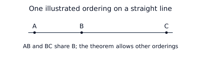
A,B,C lie on one straight line with B common to AB and BC. This is one illustrated ordering, not a restriction that B must lie between the other two points.
Open original diagram (new tab)

Ratio theorem with a common reference

Expand diagram

Use the scrollbars or arrow keys to inspect details.
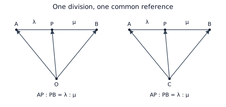
Two schematic triangles have the same A,P,B order with AP:PB=λ:μ. Their common starting point is O in one panel and C in the other. Rays to A,P,B are directed from that common reference. Equal λ and μ give the midpoint.
Open original diagram (new tab)

Internal division and lines produced

Expand diagram

Use the scrollbars or arrow keys to inspect details.
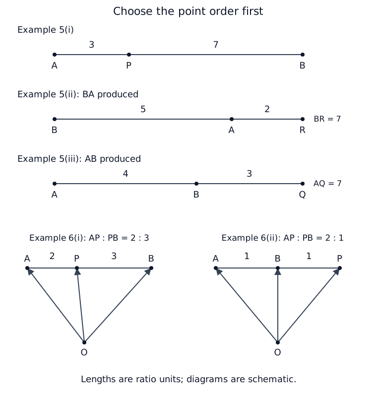
Five source cases: Example 5 has A,P,B with lengths 3,7; B,A,R with BA=5, AR=2, BR=7; A,B,Q with AB=4, BQ=3, AQ=7. Example 6 has A,P,B with AP=2, PB=3 and A,B,P with AB=BP=1. Position rays start at O in the Example 6 panels. Segment ratios, not added coordinate axes, set these schematic layouts.
Open original diagram (new tab)

Intersection of a produced line with OB

Expand diagram

Use the scrollbars or arrow keys to inspect details.
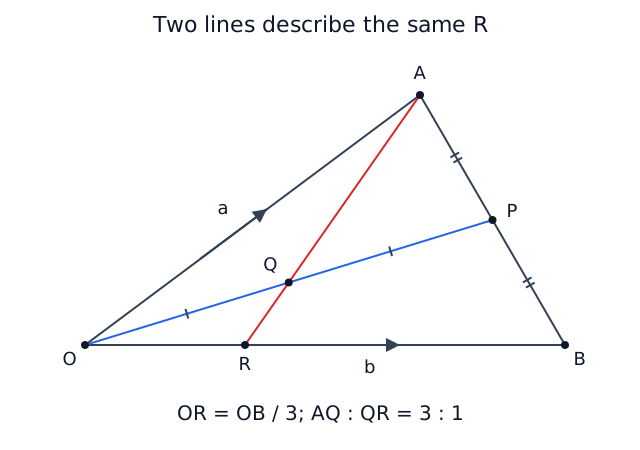
Triangle OAB with P midpoint of AB and Q midpoint of OP. A,Q,R are collinear, R lies on OB. Distinct midpoint ticks show AP=PB and OQ=QP; direction arrows label OA=a and OB=b. Result OR=OB/3 and AQ:QR=3:1.
Open original diagram (new tab)

Centroid and all three medians

Expand diagram

Use the scrollbars or arrow keys to inspect details.
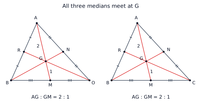
Triangle OAB has midpoints M of OB, N of OA and R of AB. All three medians meet at G. A second panel relabels O as C. Matching side ticks identify the midpoints and labels show AG:GM=2:1. The triangle is nondegenerate; the diagram imposes no coordinates.
Open original diagram (new tab)

Translate vectors to read their included angle

Expand diagram

Use the scrollbars or arrow keys to inspect details.
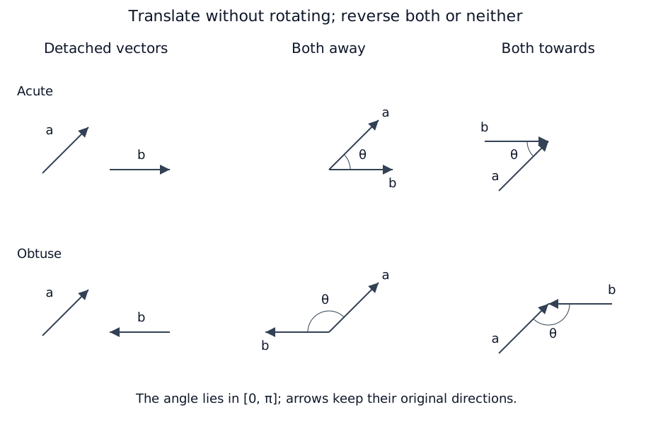
Source page 18 roles: an up-right a paired with rightward b gives an acute angle; reversing b gives an obtuse angle. Each row shows detached free vectors, a common-tail view and a common-head view. Translation preserves vector directions. Both-outgoing and both-incoming configurations give the same included angle.
Open original diagram (new tab)

Orthonormal basis and scalar products

Use mutually perpendicular unit directions. Every dot-product result is a scalar.

i:
+x
j:
+y
k:
+z
Scalar results · row first, column second
·ijk
i

11

00

00

j

00

11

00

k

00

00

11

Read the diagonal as squared unit lengths

i⋅i=∣i∣2=1\mathbf i\cdot\mathbf i=|\mathbf i|^2=1

Each basis vector has length one, so each diagonal entry is 1.

Read mixed pairs as perpendicular directions

i⋅j=j⋅i=0\mathbf i\cdot\mathbf j=\mathbf j\cdot\mathbf i=0

Different basis directions are perpendicular, so all six off-diagonal entries are zero. Reversing their order leaves a dot product unchanged.

Compare with the spatial source sketch

Expand diagram

Use the scrollbars or arrow keys to inspect details.
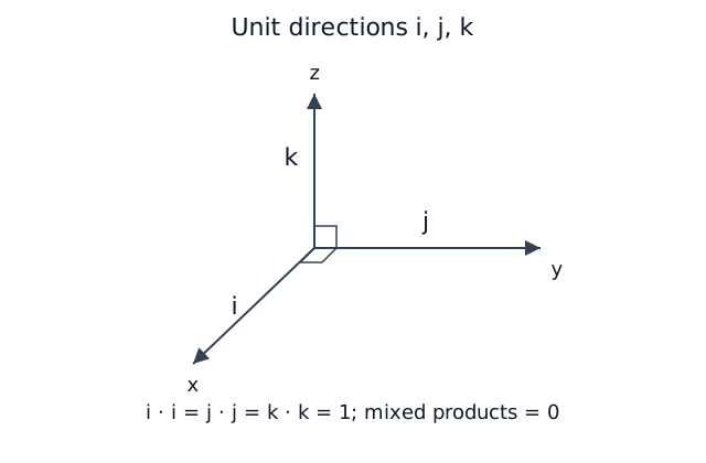
Schematic three-dimensional x,y,z axes carry unit vectors i,j,k respectively. All three pairs are perpendicular in space; self-products are 1 and mixed products 0. The y-direction is correctly labelled j, correcting the duplicated i in the source sketch.
Open original diagram (new tab)

Use the angle at the common vertex B

Expand diagram

Use the scrollbars or arrow keys to inspect details.
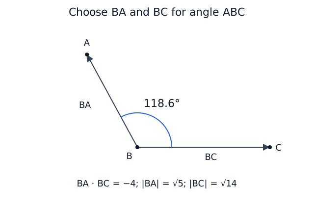
Example 13: BA and BC both point away from B, with obtuse included angle 118.6 degrees. This is a view within their plane, not a coordinate projection. Displacements BA=(0,1,2) and BC=(1,2,−3) give dot −4 and lengths√5,√14. The source acute-looking sketch is illustrative, not the numerical angle.
Open original diagram (new tab)

Direction angles with the positive axes

Expand diagram

Use the scrollbars or arrow keys to inspect details.
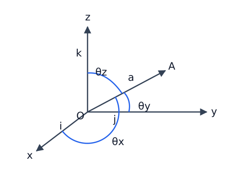
Schematic spatial x,y,z axes with positive unit directions i,j,k from O. OA is vector a; three labelled arcs theta-x, theta-y and theta-z indicate angles to the positive coordinate axes. Spatial angles are not the angles of this screen projection.
Open original diagram (new tab)

Projection in acute and obtuse cases

Compare the signed scalar, the parallel vector and the perpendicular residual. The illustration keeps the target unit direction pointing right.

Illustration: |a| = 3 units and b̂ points right. Change θ to compare signs and lengths. Values are rounded to four significant figures.

Angle θ between a and b45°
Try an example
PQRθb̂

Acute angle

The projection follows the target direction; its signed component is positive.

Signed scalar s
2.121
Parallel length PQ
2.121 units
Perpendicular length QR
2.121 units

PR represents a, PQ its parallel vector and QR its perpendicular residual. The angle θ is measured from b̂ to a.

Keep the scalar component's sign

s=a⋅b^s=\mathbf a\cdot\widehat{\mathbf b}

Use the unit direction b^=b/∣b∣\widehat{\mathbf b}=\mathbf b/|\mathbf b|, with b≠0\mathbf b\ne\mathbf0. A negative component means the projection points opposite to this direction.

Resolve the parallel vector

a∥=sb^\mathbf a_\parallel=s\widehat{\mathbf b}

The arrow PQ→\overrightarrow{PQ} follows the target direction when s is positive and reverses when s is negative. Keep the sign in the vector answer.

Find the perpendicular residual

a⊥=a−sb^\mathbf a_\perp=\mathbf a-s\widehat{\mathbf b}

Triangle addition gives PR→=PQ→+QR→\overrightarrow{PR}=\overrightarrow{PQ}+\overrightarrow{QR}. The residual QR→\overrightarrow{QR} is perpendicular to the target direction.

Take a magnitude for the parallel length

d=PQ=∣a⋅b^∣d=PQ=|\mathbf a\cdot\widehat{\mathbf b}|

PQ is a nonnegative length. The same absolute-value formula covers acute and obtuse angles.

The target vector b must be nonzero to form b̂. If a is zero, both lengths are zero and its angle has no defined direction.

Compare with the acute and obtuse source cases

Expand diagram

Use the scrollbars or arrow keys to inspect details.
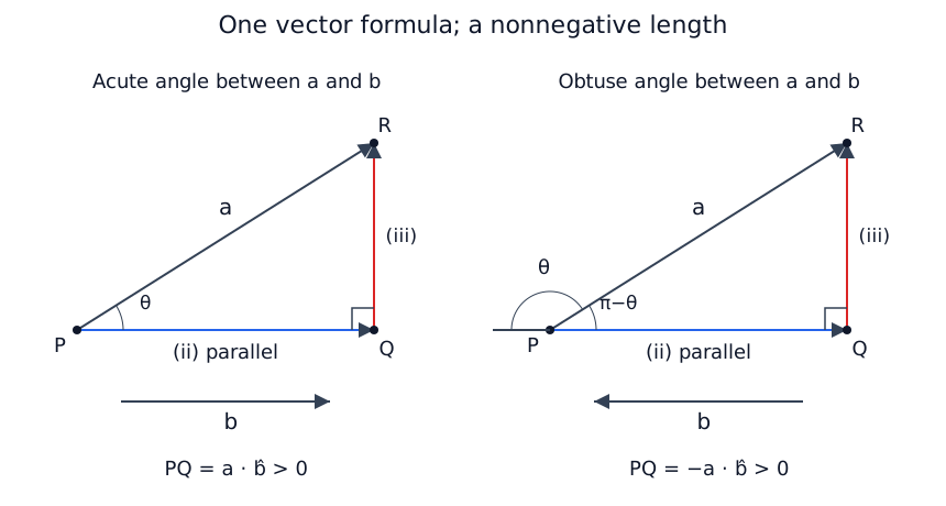
Two source triangles have PR=a and Q as the perpendicular foot. In the acute case b points from P towards Q; in the obtuse case b points left while PQ points right. The angle between a,b is θ, while the obtuse case triangle angle is π−θ. PQ is the nonnegative length; vector PQ is the parallel component (ii), QR the perpendicular component (iii).
Open original diagram (new tab)

Right-hand orientation and reversed cross products

Expand diagram

Use the scrollbars or arrow keys to inspect details.
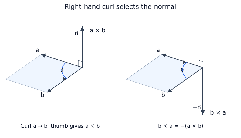
Schematic plane vectors a,b share an origin; curling from a to b picks the upward unit normal n and cross product a×b. Reversing order picks −n and b×a below the plane. Normals are perpendicular in space; screen angles are schematic. Original hand illustrations are retained in source evidence.
Open original diagram (new tab)

Cyclic products in a right-handed basis

Use a right-handed orthonormal basis. Every cross-product result is a vector.

i:
+x
j:
+y
k:
+z
Vector results · row first, column second
×ijk
i

0\mathbf0

k\mathbf k

−j-\mathbf j

j

−k-\mathbf k

0\mathbf0

i\mathbf i

k

j\mathbf j

−i-\mathbf i

0\mathbf0

Follow cyclic order

i×j=kj×k=ik×i=j\begin{aligned}\mathbf i\times\mathbf j&=\mathbf k\\\mathbf j\times\mathbf k&=\mathbf i\\\mathbf k\times\mathbf i&=\mathbf j\end{aligned}

Take two consecutive directions in the order i, j, k, then wrap back to i. The result is the remaining positive basis direction. The arrow diagram records this order; the original axes show the spatial directions.

Reverse the order to negate the vector

a×b=−(b×a)\mathbf a\times\mathbf b=-(\mathbf b\times\mathbf a)

Reversing a cyclic pair gives the opposite basis direction. The diagonal products are the zero vector because each direction is parallel to itself; zero has no unit direction.

Compare with the spatial source sketch

Expand diagram

Use the scrollbars or arrow keys to inspect details.
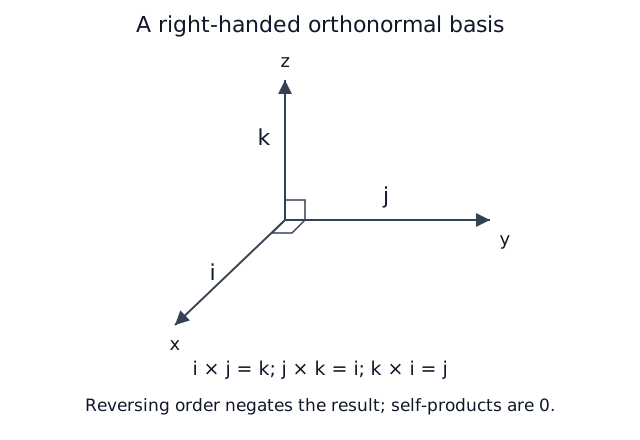
Three spatially perpendicular axes x,y,z carry i,j,k. Positive cyclic products i×j=k, j×k=i, k×i=j; reversing each order negates its result. Self-cross-products are zero. Screen projection is schematic.
Open original diagram (new tab)

Two sides and their included triangle angle

Expand diagram

Use the scrollbars or arrow keys to inspect details.
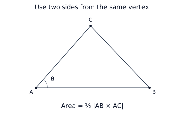
Triangle ABC has sides AB and AC with common vertex A and included angle θ. The scalar area is half the magnitude of AB×AC. No numerical coordinates or lengths are supplied.
Open original diagram (new tab)

Dot and cross products as right-triangle lengths

Compare parallel and perpendicular lengths using a unit target direction. Both lengths are nonnegative, even when the scalar component is negative.

Illustration: |a| = 3 units and b̂ points right. Change θ to compare signs and lengths. Values are rounded to four significant figures.

Angle θ between a and b45°
Try an example
PQRθb̂

Acute angle

The projection follows the target direction; its signed component is positive.

Signed scalar s
2.121
Parallel length PQ
2.121 units
Perpendicular length QR
2.121 units

PR represents a, PQ its parallel vector and QR its perpendicular residual. The angle θ is measured from b̂ to a.

The cross-product vector is normal to this plane. Its magnitude equals QR; it is a different vector from the in-plane residual.

Keep the scalar component's sign

s=a⋅b^s=\mathbf a\cdot\widehat{\mathbf b}

Use the unit direction b^=b/∣b∣\widehat{\mathbf b}=\mathbf b/|\mathbf b|, with b≠0\mathbf b\ne\mathbf0. A negative component means the projection points opposite to this direction.

Take a magnitude for the parallel length

d=PQ=∣a⋅b^∣d=PQ=|\mathbf a\cdot\widehat{\mathbf b}|

PQ is a nonnegative length. The same absolute-value formula covers acute and obtuse angles.

Read the cross-product magnitude as a height

h=QR=∣a×b^∣h=QR=|\mathbf a\times\widehat{\mathbf b}|

The cross-product vector is normal to the plane. Its magnitude equals QR; it is a different vector from the in-plane perpendicular residual.

Check the two lengths together

d2+h2=∣a∣2d^2+h^2=|\mathbf a|^2

The parallel and perpendicular components form the two legs. At a parallel boundary the height is zero, and at a right angle the parallel component is zero.

The target vector b must be nonzero to form b̂. If a is zero, both lengths are zero and its angle has no defined direction.

Compare with the source length construction

Expand diagram

Use the scrollbars or arrow keys to inspect details.
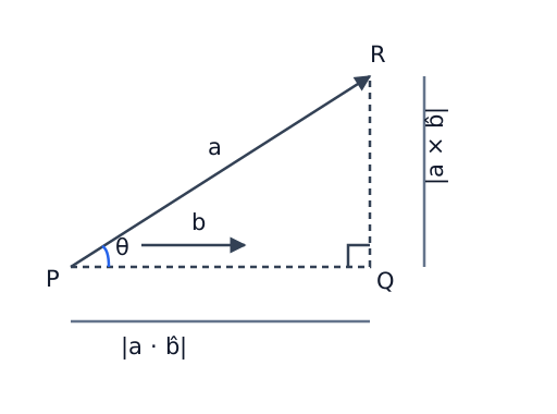
Acute right triangle PQR: directed PR is a, b points right parallel to PQ, Q is the perpendicular foot and theta is at P. A horizontal dimension gives PQ=|a dot b-hat| and a vertical dimension gives QR=|a cross b-hat|. Dashed guides and a right-angle square mark the projection. These are scalar lengths, not cross-product vector directions.
Open original diagram (new tab)

Explore

Use a=(−3,4,0)\mathbf a=(-3,4,0) and the unit directions (1,0,0)(1,0,0) and (−1,0,0)(-1,0,0). Sketch the same arrow and its perpendicular foot on the x-axis for both choices. Predict the signs of the scalar components and compare the two projection lengths, parallel vector components and perpendicular lengths. Verify with dot and cross products, explaining why a changed sign need not mean a changed geometric projection.

Related interactive example

Explore this related example, then return to the prediction task above.

The three points lie on one line

Switch parts of the scene on one at a time and read how each is found. Drag to turn the picture.

Open the interactive view to explore this geometry in 3D.

Open the full interactive problem →

Worked example

For a=(3,4,0)\mathbf a=(3,4,0), ∣a∣=5|\mathbf a|=5 and its unit vector is (3/5,4/5,0)(3/5,4/5,0). With b=(4,−3,0)\mathbf b=(4,-3,0), the dot product is zero, so the vectors are perpendicular.

A unit vector has magnitude 1, but its components need not each be 1.

Check your understanding

Let p=(2,−1,2)\mathbf p=(2,-1,2) and b=(0,3,0)\mathbf b=(0,3,0). Resolve p\mathbf p into components parallel and perpendicular to b\mathbf b. Give the signed scalar component along b\mathbf b, the projection length, and the area of the triangle whose two sides from one vertex are p\mathbf p and b\mathbf b. Explain why these quantities cannot all be read directly from p⋅b\mathbf p\cdot\mathbf b.

Practice questions

Practice section 1 · Questions 1–6

Walk a fixed distance in a vector’s direction · Find a position vector, its modulus and scaled directions · +4 more

Practice section 2 · Questions 7–12

Distinguish internal division from a line produced · Locate internal and external division points in coordinates · +4 more

Practice section 3 · Questions 13–18

Find a parameter from perpendicular vectors · Combine a known angle and a right-angle condition · +4 more

Practice section 4 · Questions 19–24

Prove the directional-cosine identity for a position vector · Separate projection length, parallel vector and perpendicular vector · +4 more

Practice section 5 · Questions 25–30

Relate parallelogram and triangle areas · Derive triangle area from three position vectors · +4 more

Practice section 6 · Questions 31–36

Expand dot products using magnitudes and an angle · Prove a projection formula in two ways · +4 more

Practice section 7 · Questions 37–42

Solve perpendicularity conditions and compare two area methods · Connect a cross-product relation to areas and a nonzero linear combination · +4 more

Practice section 8 · Questions 43–48

Distinguish four independent parameter cases · Extend a segment and use two vectors based at the angle vertex · +4 more

Practice section 9 · Questions 49–52

Use a projection foot to find a pyramid base area · Relate external division, area ratios and a unit-vector projection · +2 more

More practice

Identify whether the requested result is a scalar, vector, length or area. Predict its sign and geometric meaning before calculating, then check it independently.

Ready to try this on your own?

For “Vectors: magnitude, direction and products”, try a question without the working and explain your method. This records your confidence, saved in this browser only.

Ready to practise?Chapter practice